
Battery Charger Circuits Schematic
A Guide to Building Battery Chargers Posted by Graham Lambert | DIY Electronics | 2 In this tutorial, we will take a look at charging circuits for sealed lead acid (SLA), Nickel Cadmium (NiCd), Nickel Metal Hydride (NiMH), and Lithium Polymer (LiPo) batteries. We will provide schematics and instructions on how to build them.

14.4 Volt Battery Charger Circuit Diagram
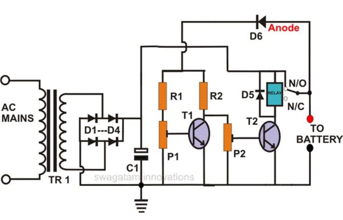
Circuit Diagram of Automatic Battery Charger This automatic battery charger circuit is mainly involves two sections - power supply section and load comparison section. The main supply voltage 230V, 50Hz is connected to the primary winding of the center tapped transformer to step down the voltage to 15-0-15V.
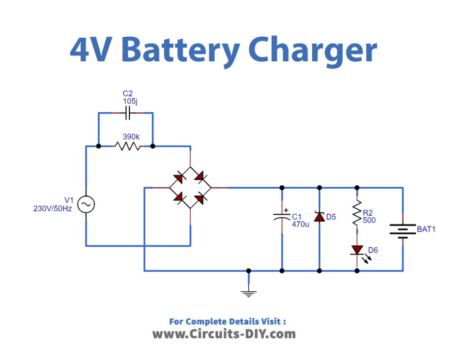
4V Battery Charger Circuit DIY Electronics
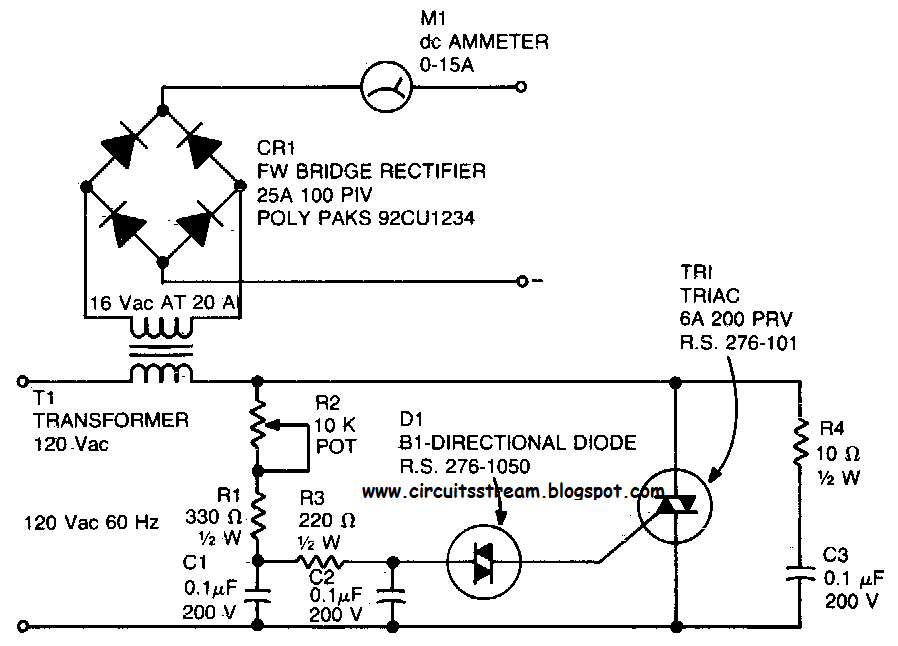
Battery charger circuit diagram with parts list Notes. At initial stages of charging the ammeter will read about 1 to 3 amperes. As the battery is slowly charged the current slowly decreases. When the battery is fully charged the ammeter reading will be zero. Always be careful to connect the charger to the battery in correct polarity.
4 Volt Battery Charger Circuit Diagram
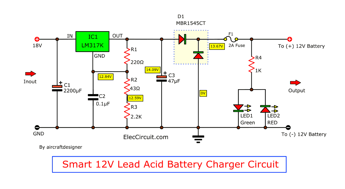
Here Battery charger circuit diagram designed by implementing adjustable voltage regulator LM317 with auto cut off feature. This circuit will give adjustable DC supply output and charges battery ranges from 6 volt to 12 Volt.

Simple 12 Volt Battery Charger Circuit Diagram
April 6, 2022 by Kiran Saleem 58,845 views Contents hide 1 Hardware Component 2 Battery Charger Circuit 3 Working Explanation 4 Applications In this tutorial, we are going to make a "Simple 12 Volt Battery Charger Circuit Diagram". To charge batteries, we need to put a voltage across the terminals, and the battery starts charging.

12v 7ah Battery Charger Circuit Diagram Pdf bestuload
Lithium Ion Battery Charger Circuit (with Diagrams) T.K. Hareendran - 03/06/2014 Here is a tried and tested sample circuit of a Li-Ion battery charger that can be used to [.] 6V, 24V, 48V External Battery Charger Control Jim Keith - 12/10/2013 This is an extension of the previously published External Battery Charger Control (12V).
Clark 24v Dc Charger Circuit Diagram
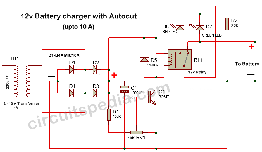
Schematic diagram circuit 1 10 amp battery charger circuit diagram Circuit 2 Circuit 3 This 12-battery charger circuit provides an Automatic cut-off facility when the battery gets fully charged. Before the use of this circuit, you need to adjust the Cut off-voltage range for the auto cut.

Regulated Car Battery Charger Circuit for Garage Mechanics Homemade Circuit Projects
Block diagram of simple constant current regulator battery charging circuit. (Image: ON Semiconductor) General Li-ion charging considerations With appropriate caution, the CCR battery charger shown above could be used to charge a Li-ion battery.
Battery Charger 12v Circuit Diagram
How the simple battery charger circuit works - The charging circuit is created around voltage regulator IC 7815 and a couple of BC transistors 547 BJTs. - The main 230V or 110V input could be the first steped down through a step-down transformer, after that it may be rectified and filtered.
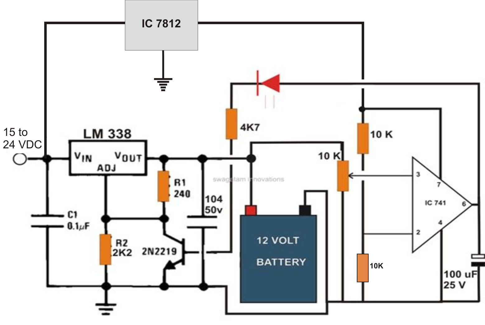
12 Volt Battery Charger Circuit Diagram With Auto Cut Off Switch Wiring Diagram
So What does the Graph Basically Suggest? Use an input supply which has a fixed current and fixed voltage output, as discussed above. (Typically this can be = Voltage 14% higher than printed value, Current 50% of the Ah value, lower current than this will also work nicely, although charging time will increase proportionately)

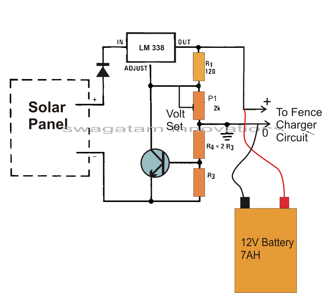
48V Solar Battery Charger Circuit with High/Low Cutoff Circuit Diagram Centre
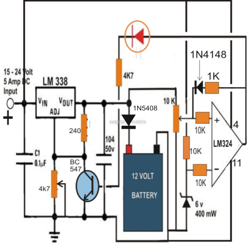
Circuit Adjustments To adjust the circuit for 12V batteries replace the battery in the circuit with an adjustable power supply. A 12V battery shows 14.4V on DMM when fully charged, so set 14.4V on the power supply. Adjust the 10K variable resistor until the green LED glows.
Self Regulating Lead Acid Battery Charger Circuit Electronic Circuit Projects
A 12v 10a SMPS battery charger circuit diagram usually consists of several essential components, including a rectifier, a power factor correction (PFC) circuit, a DC-DC converter, and a feedback control loop. The rectifier converts alternating current (AC) from the main power supply into direct current (DC), while the PFC circuit ensures that.
12v 5a Battery Charger Circuit Diagram
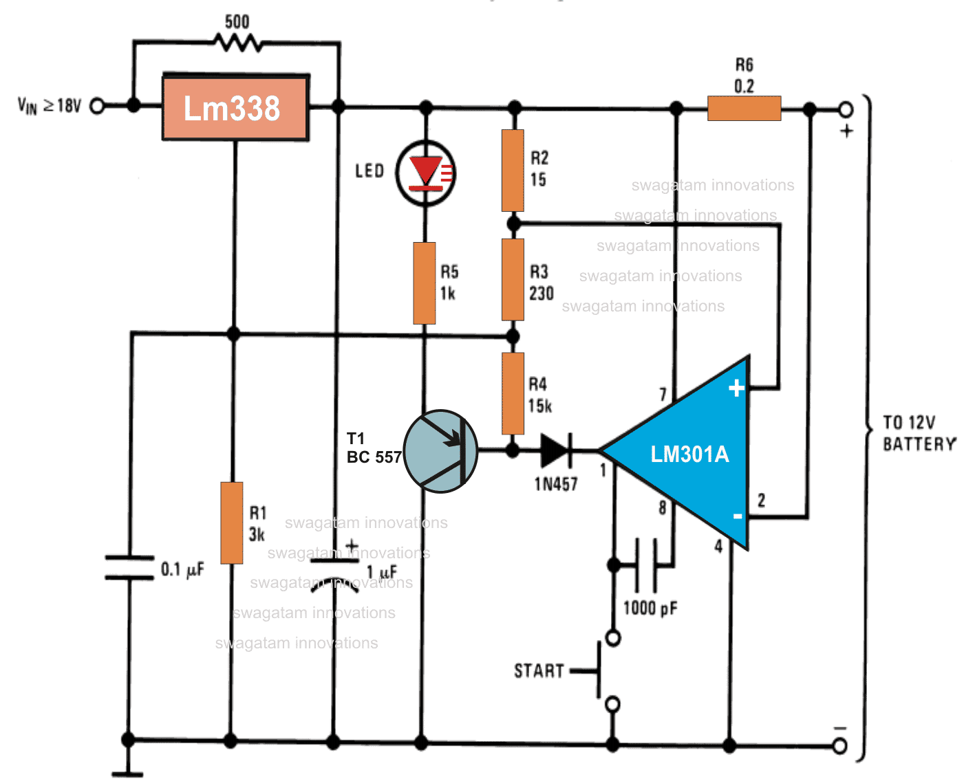
12V Battery Charger Circuits [using LM317, LM338, L200, Transistors] Last Updated on November 22, 2023 by Swagatam 170 Comments In this article we will be discussing a list of simple 12V battery charger circuits which are very easy and cheap by its design yet extremely accurate with its output voltage and current specs.
60 Volt Battery Charger Circuit Diagram
Overvoltage charging Normally, the battery manufacturer usually prints the appropriate voltage. We should use a constant voltage charge. —12V battery maximum voltage of 14.8V, Standby use is 13.8V —6V battery maximum voltage of 7.5V, Standby use is 6.8V High current fast charge But hot— So you should use initial current less 30%.
12 Volt Car Battery Charger Circuit Diagram
Prevent mistakes by downloading my DESIGN REVIEW CHECKLISTS for the schematic circuit, PCB layout, and enclosure 3D model design: https://predictabledesigns..

Super Universal Battery Charger Circuit Diagram Electronic Circuit Diagrams & Schematics
Learn about multi-stage battery chargers, how they're used, and the circuit diagrams needed to build one yourself. Project Three-stage battery chargers are commonly referred to as smart chargers. They are high-quality chargers and are popular for charging lead-acid batteries.